Obstacle Avoidance Robot with Raspberry Pi 4
Build an autonomous two-wheeled robot
Written By: Cherie Tan
Difficulty
Medium
Steps
14
Building a pre-programmed robot in a few lines of code is cool, but building an obstacle-avoidant, autonomous Raspberry Pi robot is even cooler!
In this guide, we'll show you how to incorporate a HC-SR04 Ultrasonic distance sensor to the Raspberry Pi robot. It will be programmed with Python using GPIO Zero.
In this guide, we'll show you how to incorporate a HC-SR04 Ultrasonic distance sensor to the Raspberry Pi robot. It will be programmed with Python using GPIO Zero.
After completing this guide, you will have a fully autonomous obstacle-avoidant two-wheeled robot.
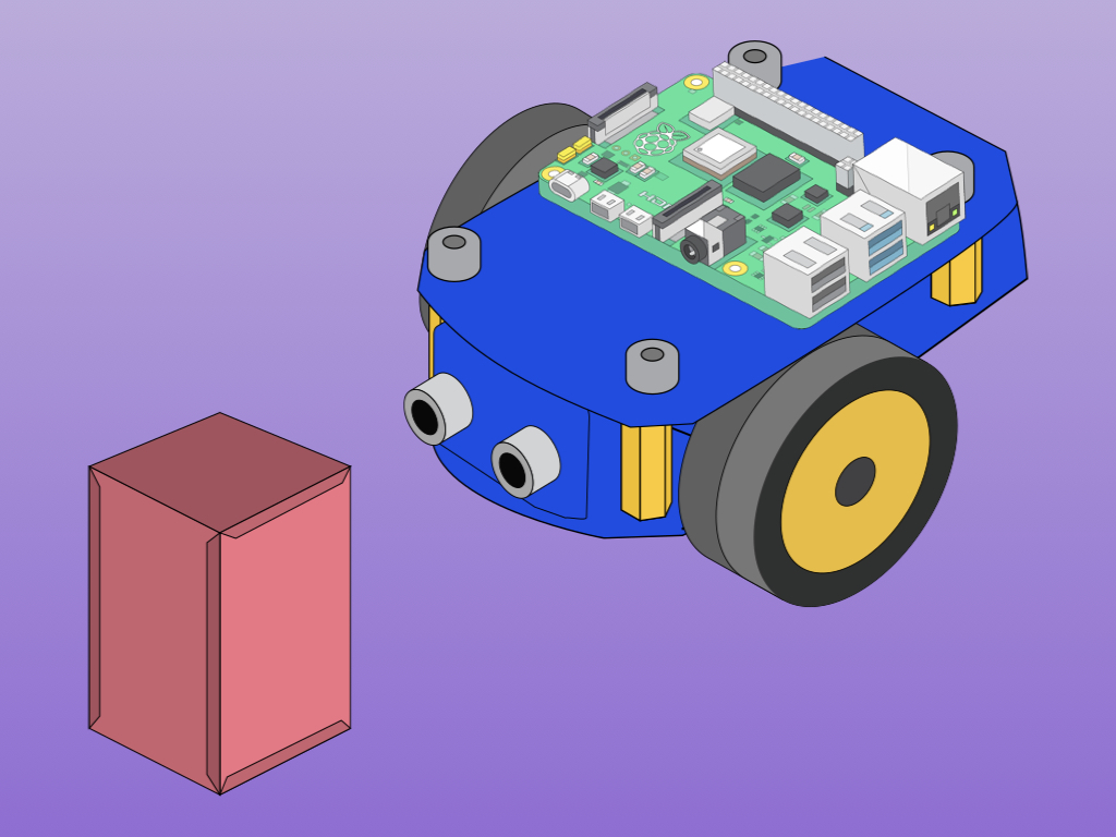
This guide continues on from the previous, where we had built a two-wheeled robot with the Raspberry Pi 4. The little two-wheeler as it is right now is vulnerable to all kinds of hazards while it is moving across the floor. Rather than pre-program it to move certain directions, why not enable it to roam autonomously and avoid obstacles on its own?
To add an obstacle avoidance feature to the robot, a HC-SR04 Ultrasonic sensor will be used. It works in a similar way that bats, dolphins and submarine sonar do, through echolocation.
Echolocation involves the use of sound waves and echoes to determine where objects are in space. When a bat produces sound waves, these may hit objects and bounce off before returning to the bat's ears. Likewise, we will use the ultrasonic sensor to determine the distance between the robot and hazards.
The HC-SR04 ultrasonic distance sensor is comprised of a transmitter, a receiver, and other circuitry but the transmitter and receiver parts are the most visible, the protrusions resembling eyes.
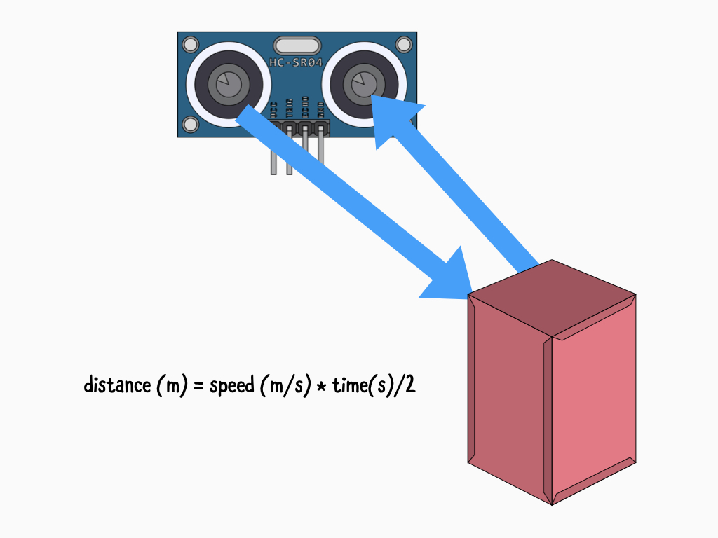
To determine the distance, it emits high-frequency ultrasonic sound which then bounces off nearby solid objects and is reflected back to the sensor. This is picked up by the receiver part of the HC-SR04. As mentioned, it works through echolocation much like bats and dolphins do!
While we will be using GPIO Zero, which simplifies the code required for our obstacle-avoidant robot, it is useful to understand just how it works. Just how is the distance between the object and sensor found? We can use the relationship between speed, distance and time. Since we know that the speed of sound in air is about 343 metres per second, we just need to know how long the sound wave takes to bounce off an object. However, we divide the time by 2 because the sound wave actually travels double the distance from the sensor to the object. Remember, it travels to the object and then back to the sensor.
To power the sensor, a 5V source is required on its VCC pin. While the HC-SR04 operates at 5V, the Raspberry Pi's GPIO pins work with 3.3V and are not 5V tolerant.
When the HC-SR04 module receives a bounce-back pulse, the Echo pin is set to a 5V logic HIGH. However, as mentioned, the GPIO pins are not 5V tolerant so if we were to connect this directly to the Raspberry Pi, it may cause damage.
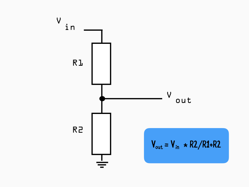
So, a voltage divider is required in our circuit to turn a larger voltage into a smaller one. Doing so, the sensor output voltage will be lowered to a value that the Raspberry Pi can handle.
To calculate the exact R1 and R2 resistor values required, we just need the desired output voltage. In this case, the desired output voltage is 3.3V
The R1 and R2 resistor values aren't actually what matters. What matters is the ratio of R1 and R2. So, let's start by choosing a comon resistor value of 2 k ohms for R1. Next, using the equation to solve for R2:
R2 = (Vout x R1) / Vin - Vout
R2 = 3.3 x 1000 / 5 - 3.3
R2 = 1941.176470 ohms
The closest common resistor value to the result would be 2000 or 2k ohms. Our second resistor value will be 2k ohms.
R2 = (Vout x R1) / Vin - Vout
R2 = 3.3 x 1000 / 5 - 3.3
R2 = 1941.176470 ohms
The closest common resistor value to the result would be 2000 or 2k ohms. Our second resistor value will be 2k ohms.
Vout is the target voltage, that is the voltage we want which is 3.3V
Vin is the voltage emitted by the Echo pin, this is the voltage (5V) that needs to be reduced.
R1 is the first resistor in our circuit, here we have chosen a 1k ohm resistor
R2 is the second resistor which we have found to be 2k ohms for our circuit.
Vin is the voltage emitted by the Echo pin, this is the voltage (5V) that needs to be reduced.
R1 is the first resistor in our circuit, here we have chosen a 1k ohm resistor
R2 is the second resistor which we have found to be 2k ohms for our circuit.
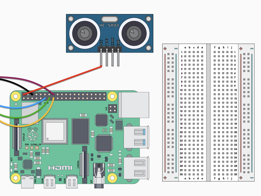
Attach a F-F jumper wire from the VCC pin on HC-SR04 Ultrasonic distance sensor to 5V on the Raspberry Pi 4.
This circuit continues on from the final circuit found in the two-wheeled robot with Raspberry Pi 4 guide.

Attach a F-M jumper wire from the GND pin on HC-SR04 Ultrasonic distance sensor to the Ground rail on the breadboard.
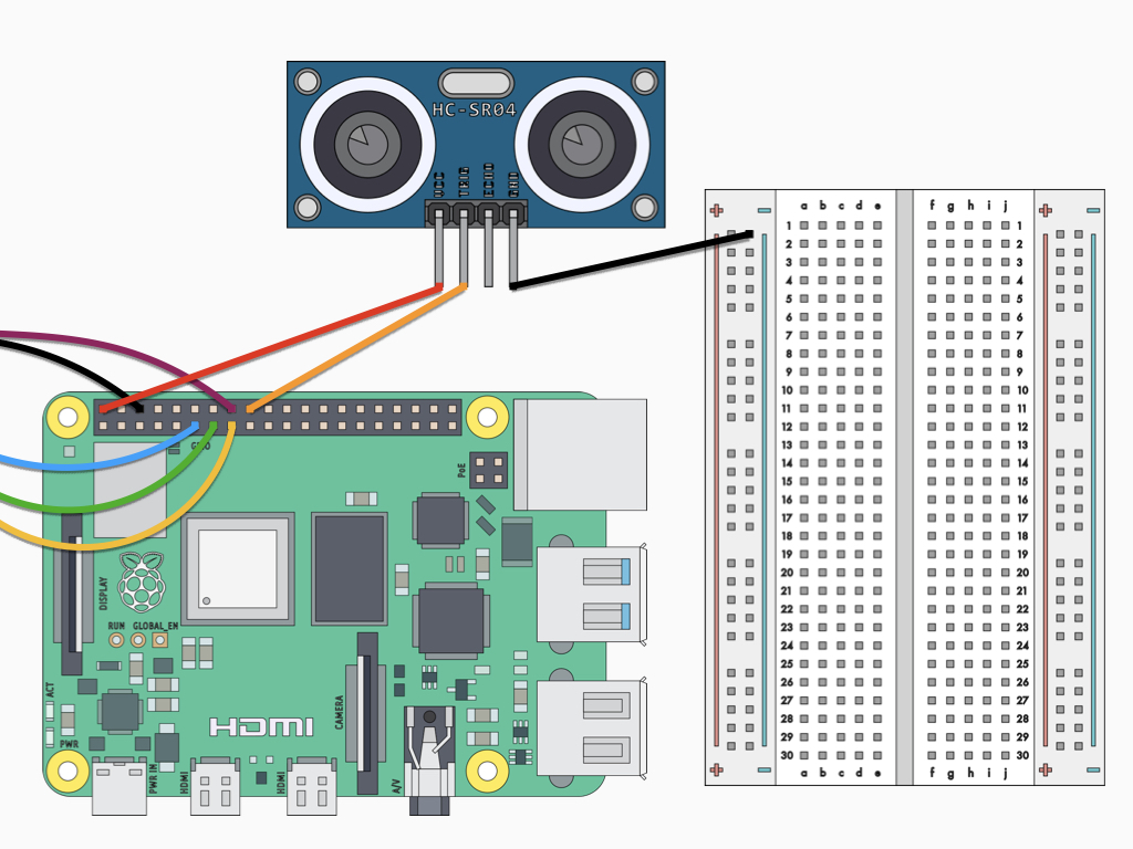
Attach a F-F jumper wire from the Trig pin on HC-SR04 Ultrasonic distance sensor to GPIO24 on the Raspberry Pi 4.
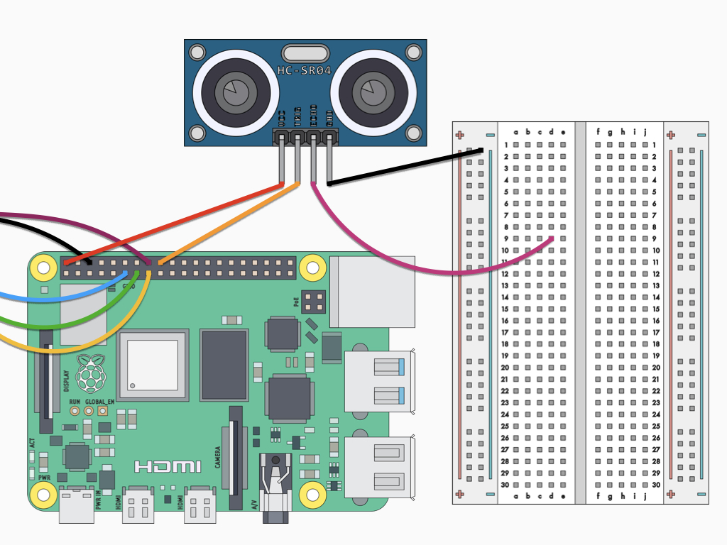
Attach a F-M jumper wire from the Echo pin on HC-SR04 Ultrasonic distance sensor to D9 on the breadboard
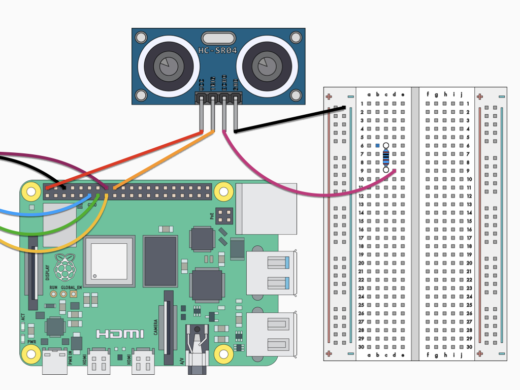
Insert a 1 k ohm resistor into C6 and C9 on the breadboard.
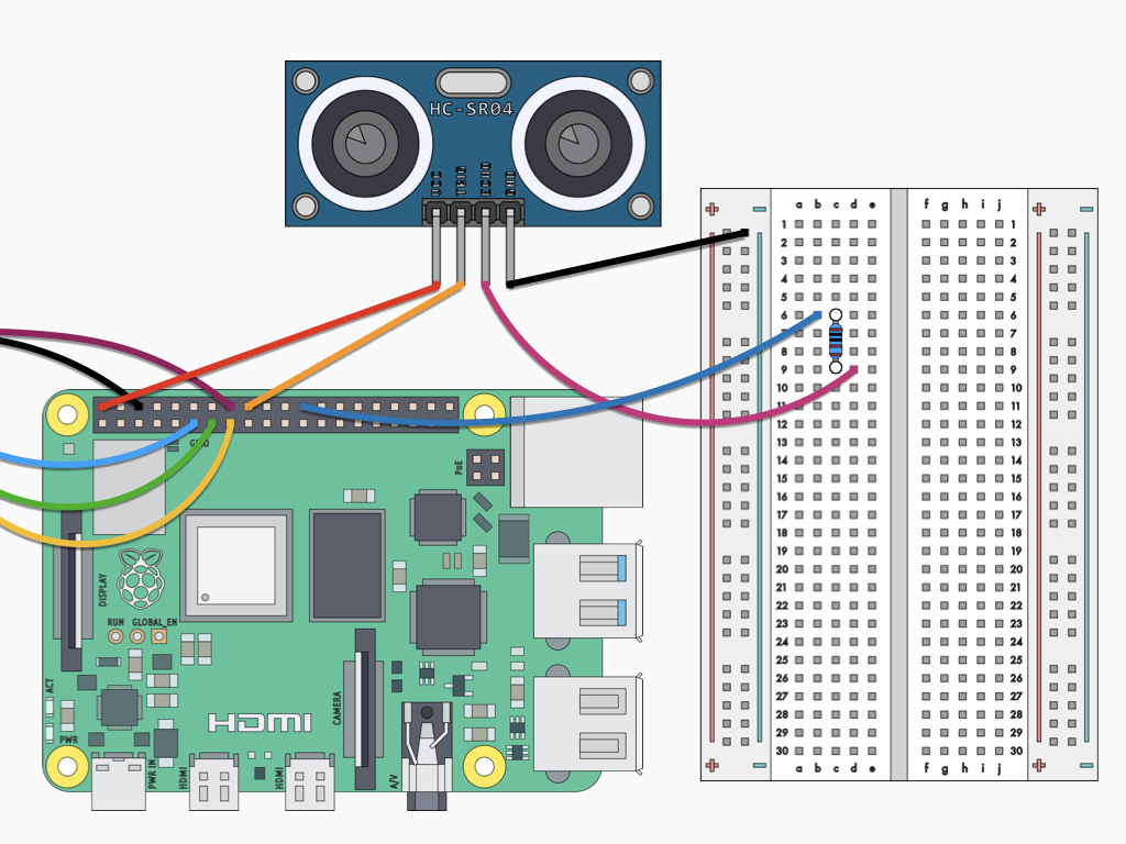
Insert a jumper wire into B6 on the breadboard and connect the other end to GPIO8 on the Raspberry Pi 4.

Insert one end of the 2.2 k ohm resistor to the same row as the 1k ohm resistor.
Connect other end of 2.2 k Ohm resistor to ground rail
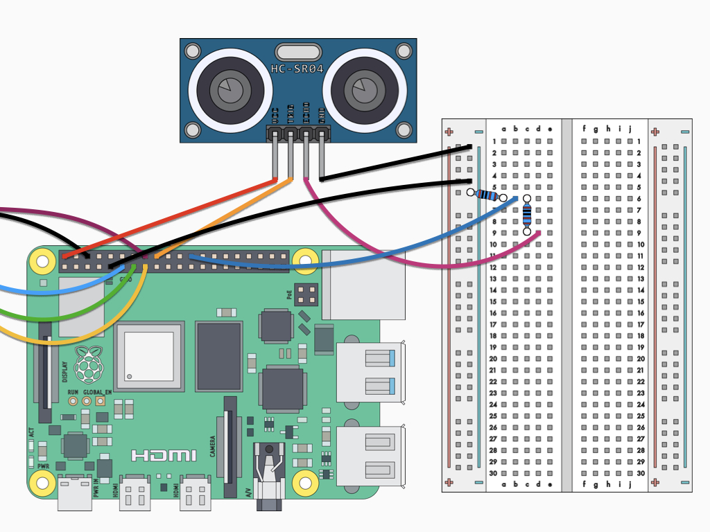
Finally, connect a F-M jumper wire between GND on the Raspberry Pi and the ground rail on the breadboard.
from gpiozero import DistanceSensor
from time import sleep

sensor = DistanceSensor(echo=8, trigger=24)

while True:
    print('Distance: ', sensor.distance * 100)
    sleep(1)
Power up the Raspberry Pi 4 and then open up the Thonny IDE or write the code using the nano editor from the terminal. Let's start by getting a reading from the HC-SR04 sensor.
The following code uses GPIO Zero, which is a zero-boilerplate Python library. The program begins with importing the necessary libraries. Then a DistanceSensor object is created and assigned to the variable, sensor. The echo and trigger pins are specified according to how they have been wired up in our circuit - echo pin to GPIO8 and trigger pin to GPIO24. Then, while the program is running, it will print the distance from sensor to object in centimetres every second.
class gpiozero.DistanceSensor(echo, trigger, *, queue_len=30, max_distance=1, thresh- old_distance=0.3, partial=False, pin_factory=None)
The DistanceSensor object has various parameters:
The DistanceSensor object has various parameters:
- echo – The GPIO pin which the ECHO pin is connected to. S
- trigger – The GPIO pin which the TRIG pin is connected to.
- queue_len – The length of the queue used to store values read from the sensor. This defaults to 30.
- max_distance – The reports a float value between 0 (too close to measure) and 1 (maximum distance). This parameter specifies the maximum distance expected in meters. This defaults to 1.
- threshold_distance – Defaults to 0.3. This is the distance (in meters) that will trigger the in_range and out_of_range events when crossed.
- partial – When false, the object will not return a value for is_active until the internal queue has filled with values. Only set this to True if you require values immediately after object construction.
- pin_factory – This is an advanced feature which most users can ignore.
Save the code. Then run it by clicking on the Run button in Thonny IDE, or by typing python yourprogramname.py in the terminal window.
The obstacle avoidance robot is now complete! In the next guide, learn how to add a line-following sensor to the robot so that it can detect edges. This will enable it to avoid falling off high surfaces. Then, create a WiFi controlled robot by adding a Raspberry Pi camera module.
For more Raspberry Pi projects, check out https://www.littlebird.com.au/a/how-to/#raspberrypi to learn even more. Happy hacking!
from gpiozero import DistanceSensor
from gpiozero import Robot
from time import sleep

robot = Robot(left = (27, 17), right = (22, 23))
sensor = DistanceSensor(echo=8, trigger=24)

while True:
  distance_to_object = sensor.distance * 100
  print distance_to_object
  if distance_to_object  <= 25:
    robot.backward()
    sleep(1)
    robot.left()
    sleep(1)
  else:
    robot.forward()
    sleep(0.1)
In this program, as before, we've used GPIO Zero. Likewise, we created a single DistanceSensor object, specifying the trigger and echo pins.
A Robot object has been created, this object is a 2-tuple containing the robot's left and right motor values; these values would be the GPIO pins they are connected to.
Then we can calculate the distance from an object using sensor.distance which gives a value in metres. We have multiplied it by 100 for a value in centimetres, this is then placed in a new variable, distance_to_object.
When the distance from an object is less than or equal to 25cm, the robot will move backwards for 1 second before moving left for another second. This will have it avoid obstacles in its way. If the distance from an object is more than 25cm, then the robot will keep moving forwards.
Copy and paste this code into the editor.
Save and run the program.