Breath Pacer with EagLED
Create a breath pacer to monitor your relaxation level
Written By: Cherie Tan

Difficulty
Medium
Steps
12
We usually think about our pulse as being a constant value measured in beats per minute (BPM). But in reality, BPM is a measure of the average of some beats over time. That's right, your heart doesn't actually beat with the regularity of a metronome or clockwork. In actuality, it speeds up and slows down as your activities vary throughout the day.
In this guide, learn to measure BPM with the EagLED, a Pulse Sensor Amped, and an Addressable RGB LED Ring (24 LEDs).
Complete this guide to create your own breath pacer device.
We usually think about our pulse as being a constant value measured in beats per minute (BPM). But in reality, BPM is a measure of the average of some beats over time. That's right, your heart doesn't actually beat with the regularity of a metronome or clockwork. In actuality, it speeds up and slows down as your activities vary throughout the day.
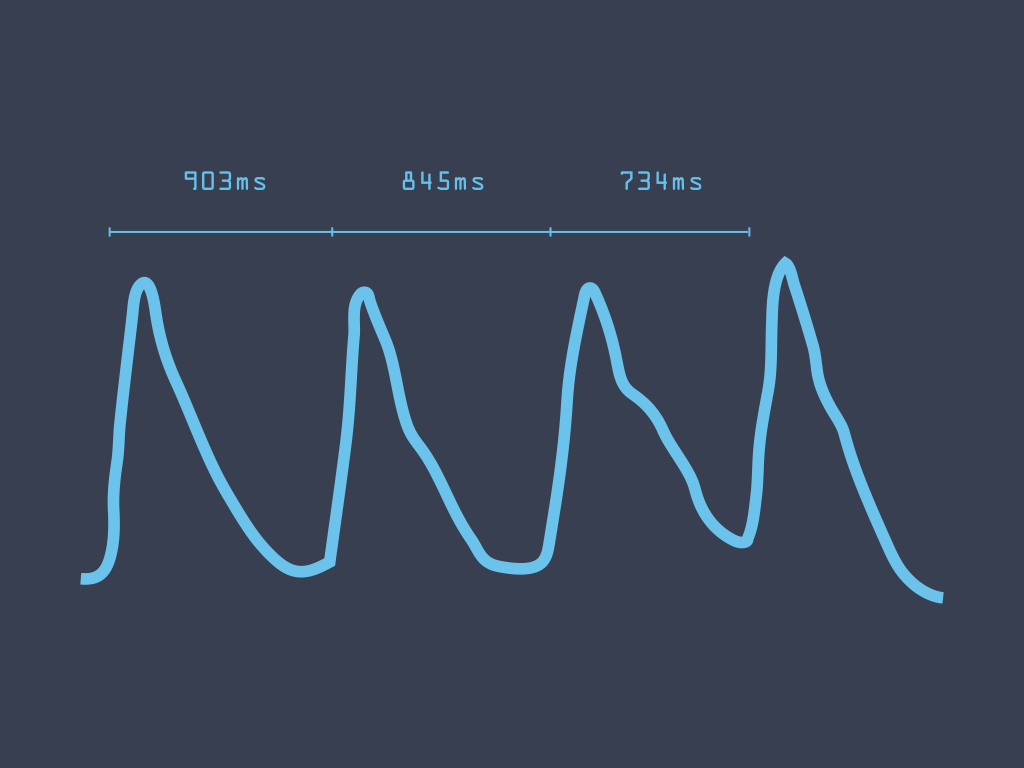
This interval between beats, also known as inter-beat interval or IBI for short, fluctuates. The first image to the left is an example of inter-beat intervals in milliseconds.
This project uses the EagLED board and a Pulse Sensor Amped to measure heart beats per minute (BPM). Then this measurement and an RGB LED ring will be used to create a breath pacer device. The goal of this project is to create a breath pacer device that can be used to reduce anxiety and increase calm.
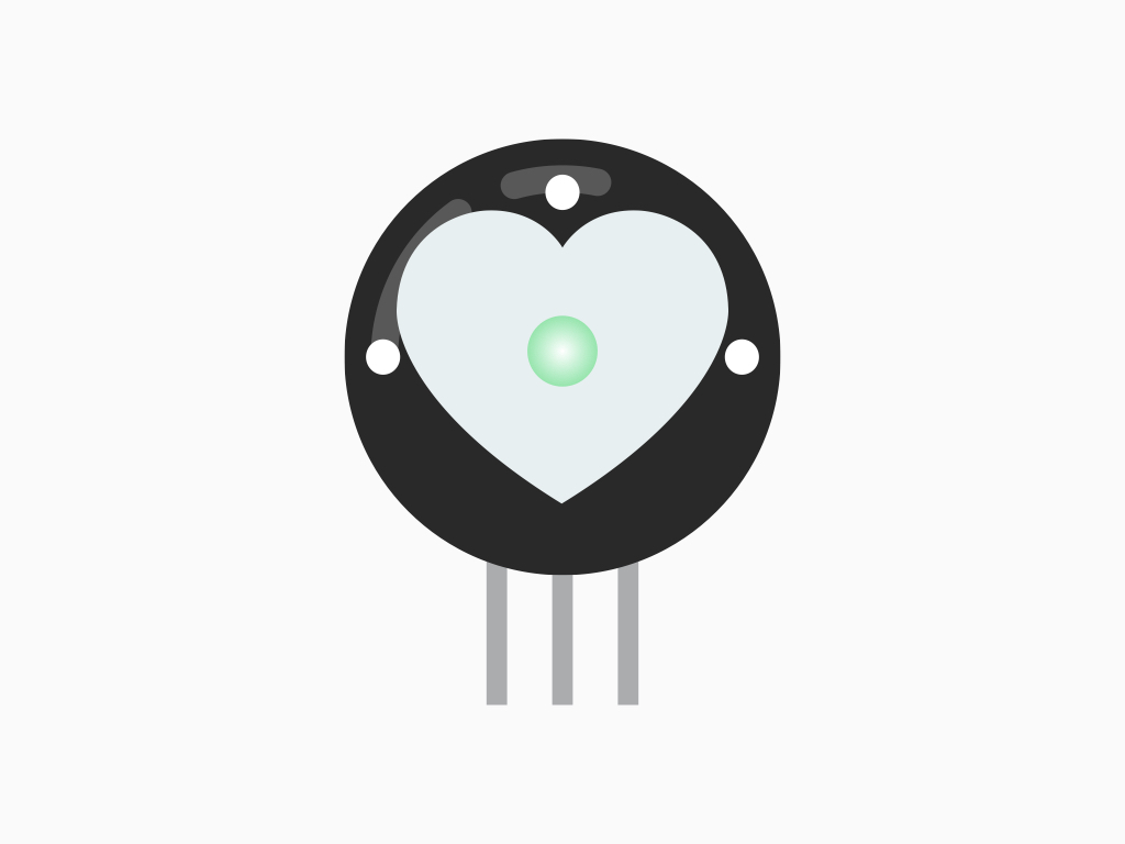
The Pulse Sensor Amped works by using photoplethysmography (PPG), which measures differences in light absorption. This is a technique used for non-invasive heart rate monitoring.
How does it work? On one side of the sensor, there is a green LED. On the other side, there is a light-sensitive diode. When placed on say your finger or earlobe, this green light penetrates the skin! Some of this green light is then reflected back to the sensor, and measured by the light-sensitive diode.
When blood pulses through your veins, more green light absorbed. In between beats, there is less green light absorbed due to the absence of blood.
When blood pulses through your veins, more green light absorbed. In between beats, there is less green light absorbed due to the absence of blood.
The heart pulse signal that comes out of a photoplethysmograph is an analog signal reflecting fluctuations in voltage:
If the amount of light incident on the sensor remains constant, then the signal value will remain close to 512.
More light and the signal goes up, less light and the signal goes down.
If the amount of light incident on the sensor remains constant, then the signal value will remain close to 512.
More light and the signal goes up, less light and the signal goes down.
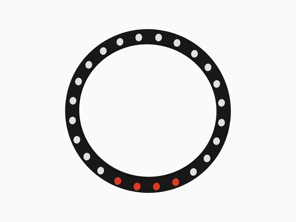
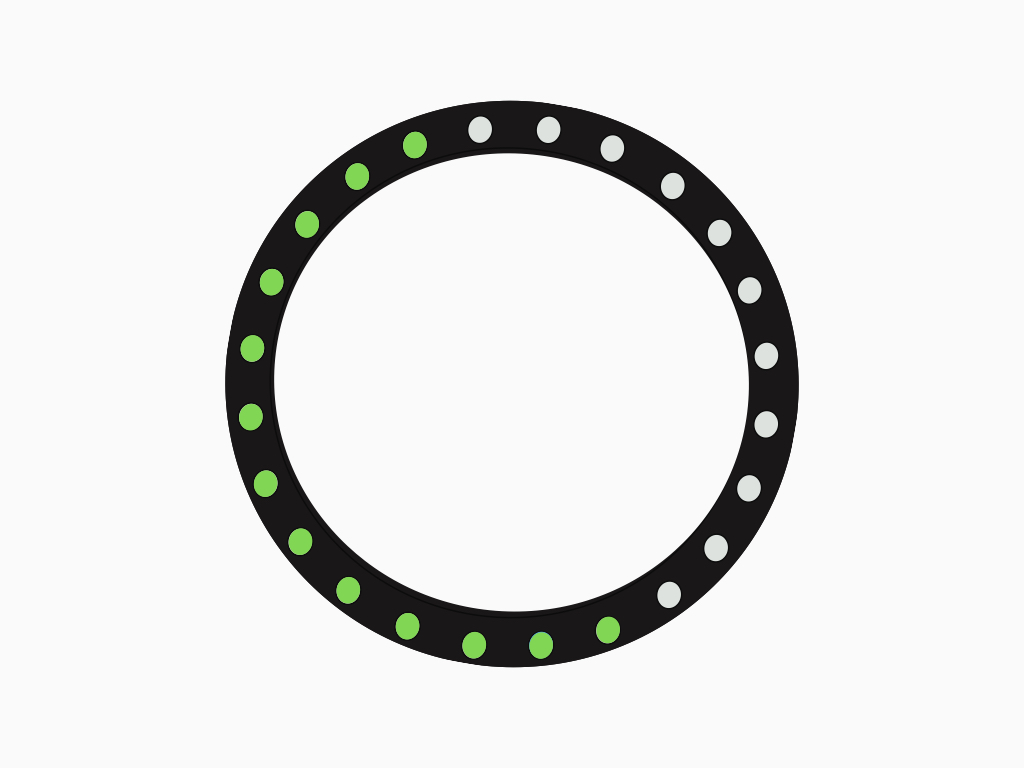
The LED ring has 24 individually addressable RGB LEDs, aligned in a circular arrangement.
In each LED package, there is a WS2812 driver which means you can control each LED individually, or chain multiple LEDs together.
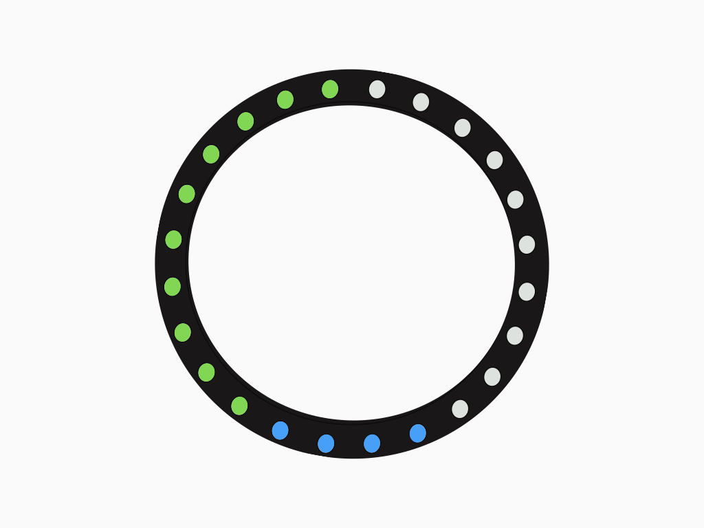
Twenty of these LEDs will display the breath pacer. The LEDs will pulse toward one side. Breathe in as it pulses from LEDs 1 to 10. Breathe out as it pulses from LED 11 to 20.
The remaining four LEDs will be used to display your level of relaxation where:
Red = low relaxation
Blue = moderate relaxation
Green = high relaxation
Red = low relaxation
Blue = moderate relaxation
Green = high relaxation
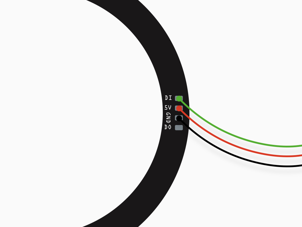
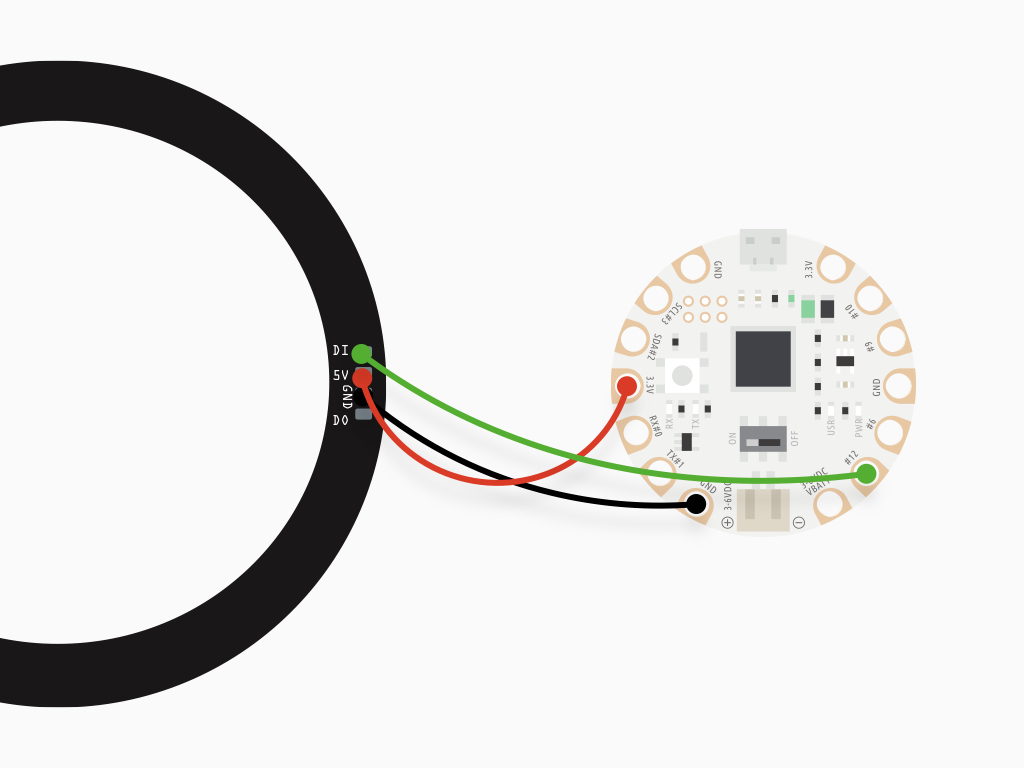
Next, solder a wire from '5V' to '3.3V'
Finally, connect 'GND' to 'GND'
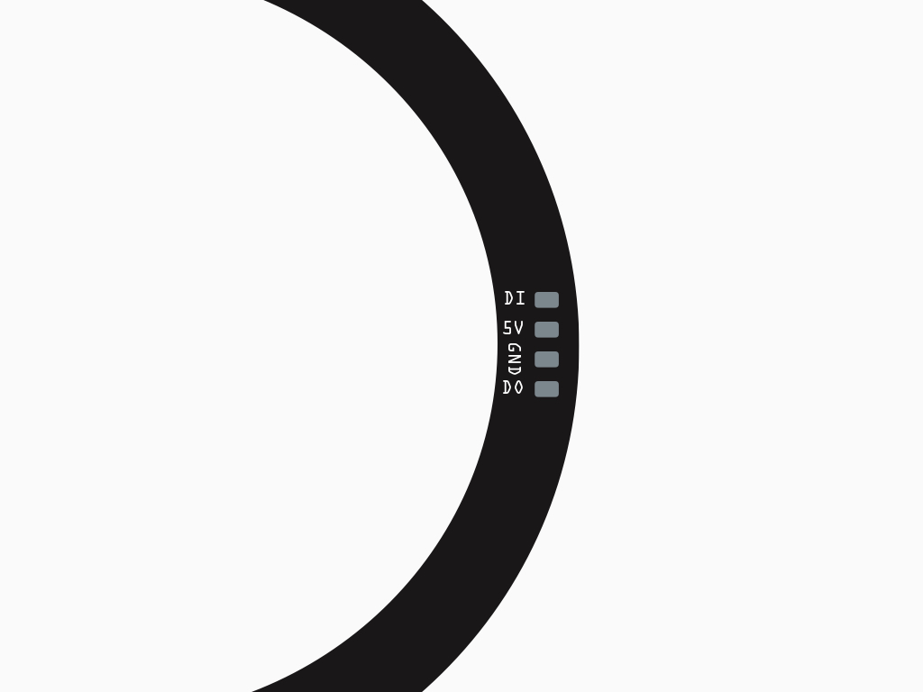
There are four connections on the RGB LED Ring:
DI - Digital Input
5V - 5 Volts
GND - Ground
DO - Digital Output
DI - Digital Input
5V - 5 Volts
GND - Ground
DO - Digital Output
First, solder a wire from 'DI' on the RGB LED ring to '#12' on EagLED
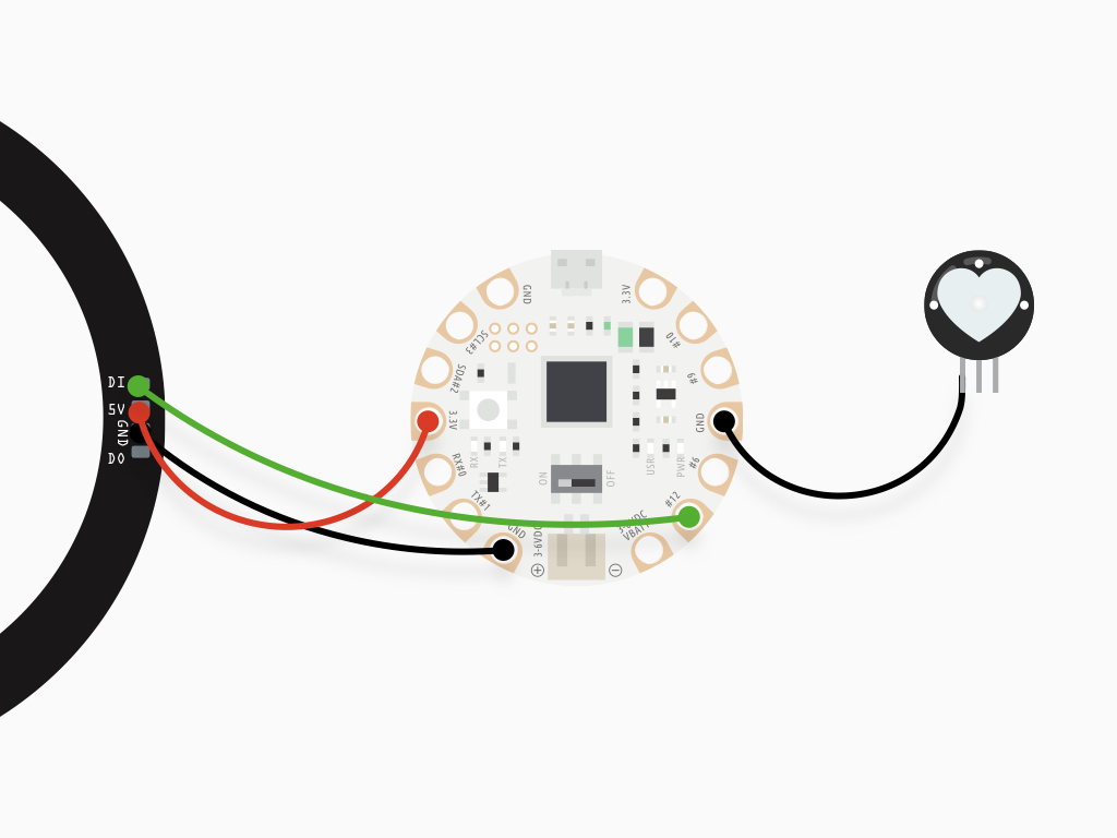
Solder wires from the Pulse Sensor Amped to EagLED. First, connect '-' of the pulse sensor to 'GND' on EagLED
Connect '+' to 'VBATT'
Connect 'S' to '#A9'
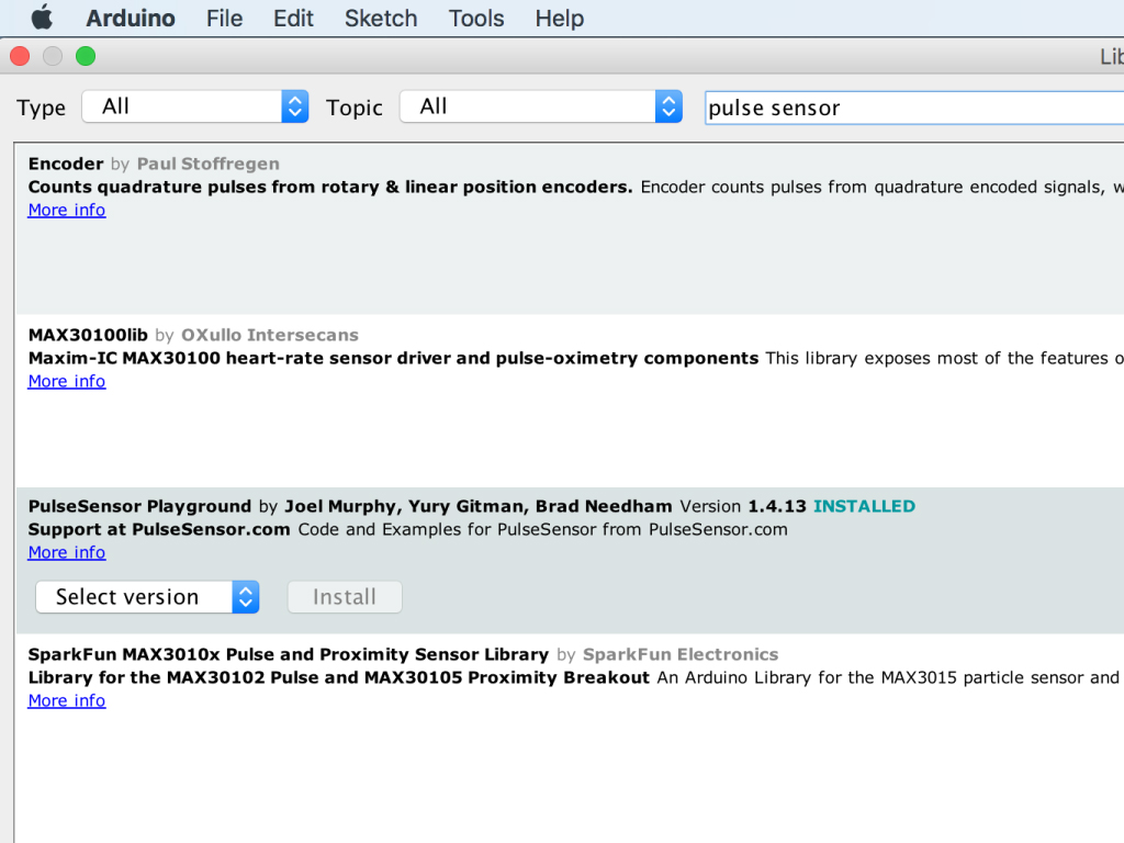
If you haven't already done so, please install the Pulse Sensor library: Go to Tools > Manage Libraries ...
Type 'pulse sensor' in the search field
Scroll down to find 'PulseSensor Playground'
Click on the 'Install' button
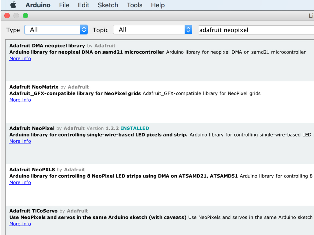
You will also need a library to use the RGB LED Ring: Type 'adafruit neopixel' in the search field
Find 'Adafruit Neopixel'
Click on the 'Install' button
#include <Adafruit_NeoPixel.h>

// Which LED_PIN on the EagLED is connected to the RGB LED Ring?
#define LED_PIN        12

// How many LEDs are attached to the EagLED?
#define BREATH_LED_COUNT 20
Adafruit_NeoPixel pixels(BREATH_LED_COUNT, LED_PIN, NEO_GRB + NEO_KHZ800);

#define DELAYVAL 500 // Time (in milliseconds) to pause between pixels

void setup() {
  pixels.begin(); // INITIALIZE NeoPixel strip object (REQUIRED)
  pixels.setBrightness(100);
}

void loop() {
  pixels.clear(); // Set all pixel colors to 'off'
  // The first NeoPixel in a strand is #0, second is 1, all the way up
  // to the count of pixels minus one.
  for (int i = 0; i < 10; i++) { // For each pixel...

    // pixels.Color() takes RGB values, from 0,0,0 up to 255,255,255
    // Here we're using a moderately bright green color:
    pixels.setPixelColor(i, pixels.Color(0, 150, 0));
    pixels.show();   // Send the updated pixel colors to the hardware.
    delay(DELAYVAL); // Pause before next pass through loop
  }

}
Connect EagLED to the computer via microUSB cable
Make sure the EagLED switch is flicked to 'ON'
Upload the following sketch to the EagLED. The RGB LED Ring's first LED to tenth LED will light up one after another.
#include <Adafruit_NeoPixel.h>

// Which LED_PIN on the EagLED is connected to the RGB LED Ring?
#define LED_PIN        12

// How many LEDs are attached to the EagLED?
#define BREATH_LED_COUNT 20
Adafruit_NeoPixel pixels(BREATH_LED_COUNT, LED_PIN, NEO_GRB + NEO_KHZ800);

#define DELAYVAL 500 // Time (in milliseconds) to pause between pixels

void setup() {
  pixels.begin(); // INITIALIZE NeoPixel strip object (REQUIRED)
  pixels.setBrightness(100);
}

void loop() {
  pixels.clear(); // Set all pixel colors to 'off'
  // The first NeoPixel in a strand is #0, second is 1, all the way up
  // to the count of pixels minus one.
  for (int i = 0; i < 10; i++) { // For each pixel...
    // pixels.Color() takes RGB values, from 0,0,0 up to 255,255,255
    // Here we're using a moderately bright green color:
    pixels.setPixelColor(i, pixels.Color(0, 150, 0));
    pixels.show();   // Send the updated pixel colors to the hardware.
    delay(DELAYVAL); // Pause before next pass through loop
  }

  pixels.clear(); // Set all pixel colors to 'off'
  for (int i = 10; i < 20; i++) { // For each pixel...
    // pixels.Color() takes RGB values, from 0,0,0 up to 255,255,255
    // Here we're using a moderately bright green color:
    pixels.setPixelColor(i, pixels.Color(0, 150, 0));
    pixels.show();   // Send the updated pixel colors to the hardware.
    delay(DELAYVAL); // Pause before next pass through loop
  }
}
Upload the following sketch to the EagLED
The RGB LED Ring's first LED to tenth LED will light up one after another.
Then the first to tenth LEDs will stop lighting up
This is then followed by the eleventh LED to twentieth LED lighting up one after another.
The eleventh to twentieth LEDs will then stop lighting up.
This loop will repeat as long as the EagLED is powered!
#define USE_ARDUINO_INTERRUPTS true    // Set-up low-level interrupts for most acurate BPM math.
#include <PulseSensorPlayground.h>     // Includes the PulseSensorPlayground Library.
#include <Wire.h>
#include <Adafruit_NeoPixel.h>

//  Variables
const int PulseWire = A9;       // PulseSensor PURPLE WIRE connected to ANALOG PIN 0
int Threshold = 550;           // Determine which Signal to "count as a beat" and which to ignore.
#define LED_PIN        12     // Pin on EagLED that RGB LED Ring is connected to
#define BREATH_LED_COUNT 24  // How many LEDs are attached to the EagLED?
#define DELAYVAL 500 // Time (in milliseconds) to pause between LEDs

Adafruit_NeoPixel pixels(BREATH_LED_COUNT, LED_PIN, NEO_GRB + NEO_KHZ800);
PulseSensorPlayground pulseSensor;  // Creates an instance of the PulseSensorPlayground object called "pulseSensor"


void setup() {
  Serial.begin(9600);          // For Serial Monitor
  pixels.begin(); // INITIALIZE NeoPixel strip object (REQUIRED)
  pixels.setBrightness(5);
  // Configure the PulseSensor object, by assigning our variables to it.
  pulseSensor.analogInput(PulseWire);
  pulseSensor.setThreshold(Threshold);
  // Double-check the "pulseSensor" object was created and "began" seeing a signal.
  if (pulseSensor.begin()) {
    Serial.println("We created a pulseSensor Object !");  //This prints one time at Arduino power-up,  or on Arduino reset.
  }
}


void loop() {
  pixels.clear(); // Set all pixel colors to 'off'
  relaxMonitor();
  breathPacer();
}

void breathPacer() {
  for (int i = 0; i < 10; i++) { // For each pixel...
    // pixels.Color() takes RGB values, from 0,0,0 up to 255,255,255
    // Here we're using a moderately bright green color:
    pixels.setPixelColor(i, pixels.Color(0, 150, 0));
    pixels.show();   // Send the updated pixel colors to the hardware.
    delay(DELAYVAL); // Pause before next pass through loop
  }
  pixels.clear(); // Set all pixel colors to 'off'
  for (int i = 10; i < 20; i++) { // For each pixel...
    // pixels.Color() takes RGB values, from 0,0,0 up to 255,255,255
    // Here we're using a moderately bright green color:
    pixels.setPixelColor(i, pixels.Color(0, 150, 0));
    pixels.show();   // Send the updated pixel colors to the hardware.
    delay(DELAYVAL); // Pause before next pass through loop
  }
}

void relaxMonitor() {
  int BPM = pulseSensor.getBeatsPerMinute();  // Calls function on our pulseSensor object that returns BPM as an "int".
  if (pulseSensor.sawStartOfBeat()) {            // Constantly test to see if "a beat happened".
    Serial.println(BPM);
    if (BPM <= 60) {
      pixels.setPixelColor(20, pixels.Color(0, 150, 0));
      pixels.setPixelColor(21, pixels.Color(0, 150, 0));
      pixels.setPixelColor(22, pixels.Color(0, 150, 0));
      pixels.setPixelColor(23, pixels.Color(0, 150, 0));
    }
    else if (BPM > 100) {
      pixels.setPixelColor(20, pixels.Color(255, 0, 0));
      pixels.setPixelColor(21, pixels.Color(255, 0, 0));
      pixels.setPixelColor(22, pixels.Color(255, 0, 0));
      pixels.setPixelColor(23, pixels.Color(255, 0, 0));
    }
    else {
      pixels.setPixelColor(20, pixels.Color(0, 0, 255));
      pixels.setPixelColor(21, pixels.Color(0, 0, 255));
      pixels.setPixelColor(22, pixels.Color(0, 0, 255));
      pixels.setPixelColor(23, pixels.Color(0, 0, 255));
    }
  }
}
Now upload the following sketch to the EagLED
You will notice that the 21st to 24th LED will light up according to your relaxation level.
A normal resting heart rate ranges from 60 to 100 beats per minute, so they will light up green if your BPM is less than or equal 60.
The LEDs will light up blue if BPM is between 61 to 100
If your BPM is over 100, then the LEDs will light up in red.
A normal resting heart rate ranges from 60 to 100 beats per minute, so they will light up green if your BPM is less than or equal 60.
The LEDs will light up blue if BPM is between 61 to 100
If your BPM is over 100, then the LEDs will light up in red.
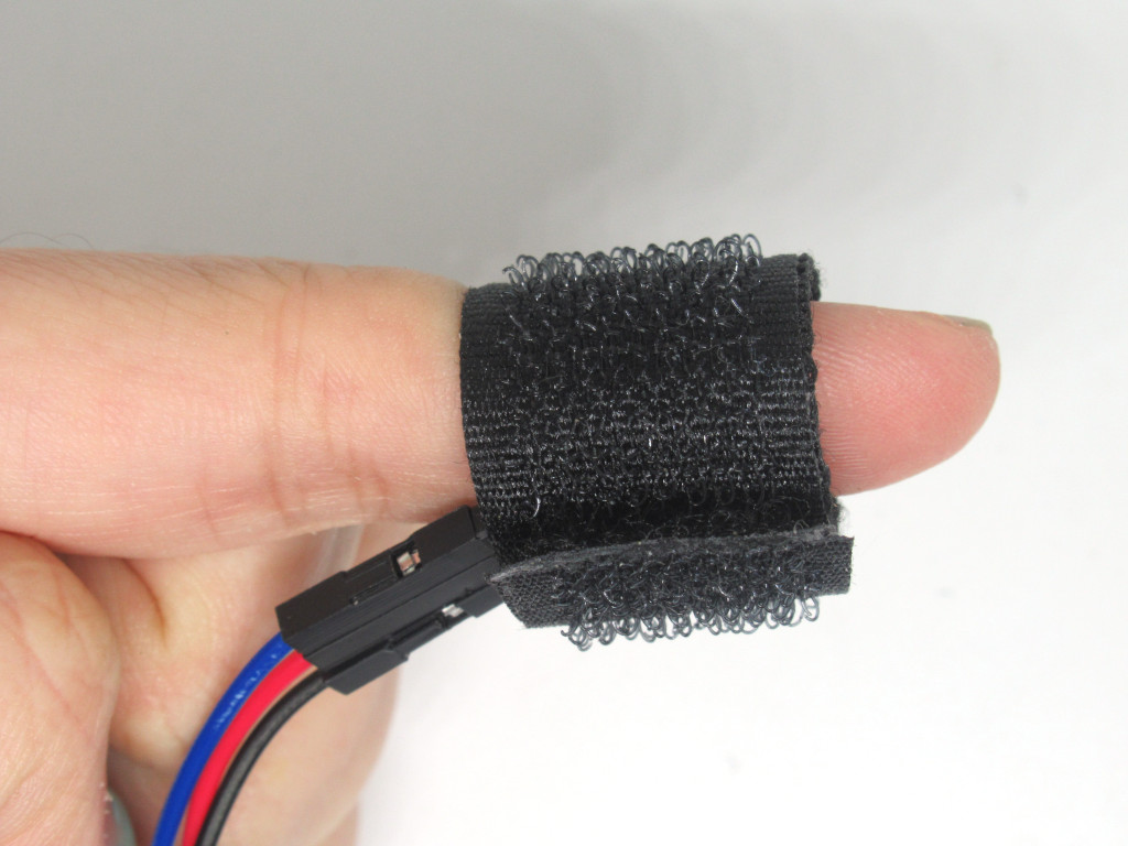
You may want to use a Velcro strap to attach the Pulse Sensor around your finger for accurate readings.


